Machinable tolerances depend on various machining methods such as cutting, sheet metal processing, and lathe work. Each machining method has its own standard for machinable tolerances, which should be understood in advance by the designers, machinists, and material handlers. This knowledge can only be beneficial. This article introduces machinable tolerances based on three main machining methods.
I. Machinable Tolerances for Resin
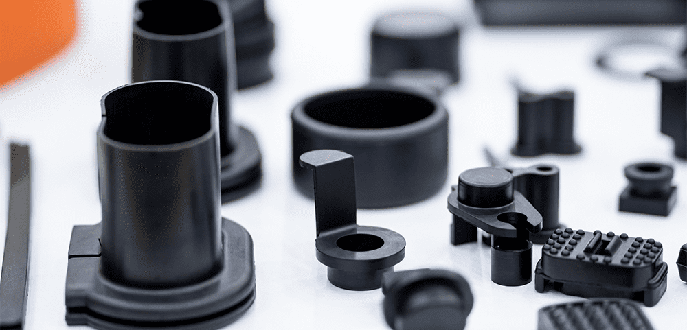
The primary machining methods for resin are machining and injection molding. Machining involves using tools to cut the resin, while injection molding is a process in which heated, molten resin is poured into a mold to cool and solidify. The accuracy of machining is generally higher than that of injection molding, allowing for stricter tolerance specifications.

For both methods, it is important to note that tolerances are measured at the temperature at which the measurement is taken, due to the presence of thermal expansion. Additionally, machinable tolerances may vary slightly depending on the material, equipment, and mold precision.
- Hole Diameter Tolerance in Machining:
For example, when drilling a hole in resin with a diameter of about 10mm, the tolerance could be around 0 to +0.03 mm. The hole size depends on the size of the drilling tool, allowing for high-precision machining. - Center-to-Center Hole Tolerance in Machining:
Materials that support high-precision machining can specify a tolerance of about ±0.01 mm. On the other hand, POM (Polyoxymethylene), known for its resistance to wear, is difficult to machine with such high precision, with a limit of around ±0.05 mm. - Hole Diameter Tolerance in Injection Molding:
When specifying a hole diameter of about 10mm and a hole depth of around 10mm, a hole diameter tolerance of about 0 to +0.05 mm can be specified. Injection molding molds often have a draft angle, so the deeper the hole, the larger the tolerance. - Center-to-Center Hole Tolerance in Injection Molding:
The machinable tolerance for POM (Polyoxymethylene) is about ±0.1 mm. Additionally, even for materials like PPS (Polyphenylene Sulfide) that are easier to machine accurately, ±0.03 mm is the limit.
II. Tolerances in Sheet Metal Processing
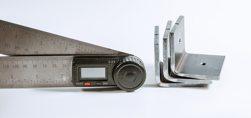
The primary machining methods for sheet metal are bending and cutting. Bending is typically done with a bending machine to bend metal sheets, usually at right angles, but other angles are also possible. Cutting is done using a laser processing machine to cut shapes, drill round holes, long holes, etc.

- Hole Diameter Tolerance in Sheet Metal Processing:
When cutting with laser processing, the hole diameter can be specified with a tolerance of 0 to +0.05 mm. For a φ10 hole used for positioning, the specification can be φ10 +0.05/0. - Center-to-Center Hole Tolerance in Sheet Metal Processing:
The center-to-center distance can be specified with a tolerance of about ±0.05 mm. - Bending Tolerance:
The dimensional tolerance from the center of the reference hole to the bending base is limited to about ±0.15 mm. It is also necessary to indicate the tolerance of the bending angle. For example, a 90° bend would require a tolerance of around ±1.0°. Even if the tolerance at the bend base is ±0.15 mm, the deviation would be greater at the top of the bend. If you also want to specify the distance from the center of the reference hole to the top of the bend, you need to consider the angle tolerance, making the tolerance at the top greater than at the base.
III. Tolerances for Lathe Processing of Bar Stock
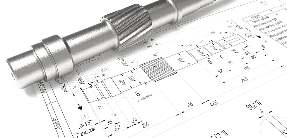
Metal bar stock is machined using a lathe. A lathe is a machine that cuts the surface of a workpiece by pressing a tool against a bar stock rotating at high speed. This primarily involves specifying the diameter and axial dimensions.

- Diameter Tolerance for SUM Material:
SUM material is a free-cutting steel that is typically used for mass production because it is cheaper than SUS. SUM material is coated with anti-rust oil or plating to prevent rust. Since the thickness of the plating also varies, if plating is included, the tolerance range is limited to around 0.03 mm. The specification would be φ100 / -0.03. - Diameter Tolerance for SUS Material:
For SUS material, plating is not required, allowing for slightly tighter tolerances. A specification of about φ100 / -0.01 mm can be given, with a tolerance range of around 0.01 mm. - Tolerance in the Longitudinal Direction:
The dimensional tolerance in the longitudinal direction can be specified as approximately ±0.03 mm.
